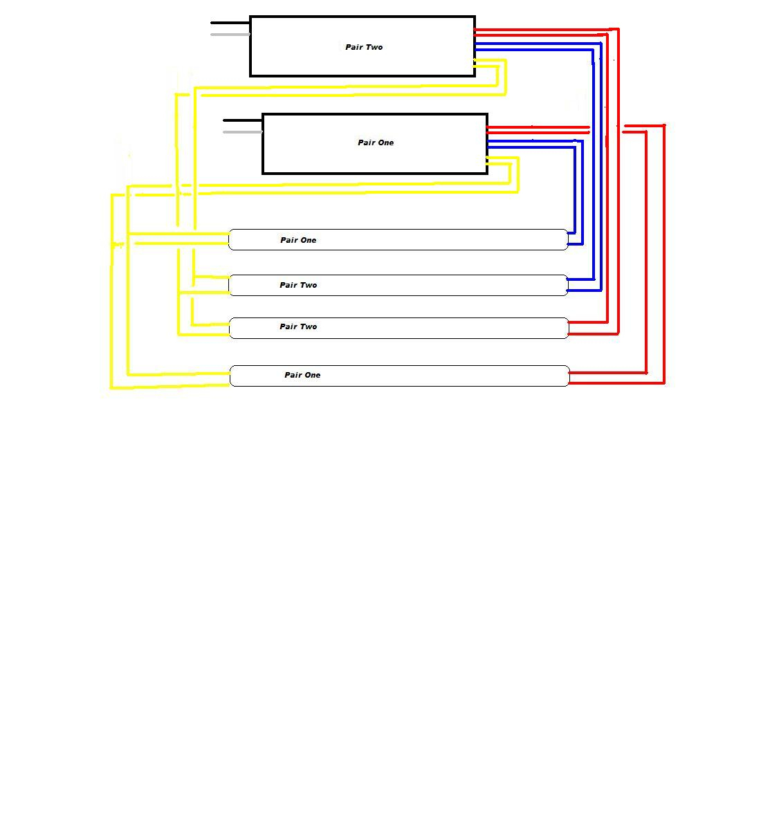
1 Lamp T12 Ballast Wiring Diagram
The battery is rated for 90 minutes of run time per osha standards/5 (39). Injunction of two wires is usually indicated by black dot in the junction of 2 lines.
What is the ballast wiring set up when converting from a T12 ballast to a T8 electronic
There will be primary lines that are represented by l1, l2, l3, and so on.
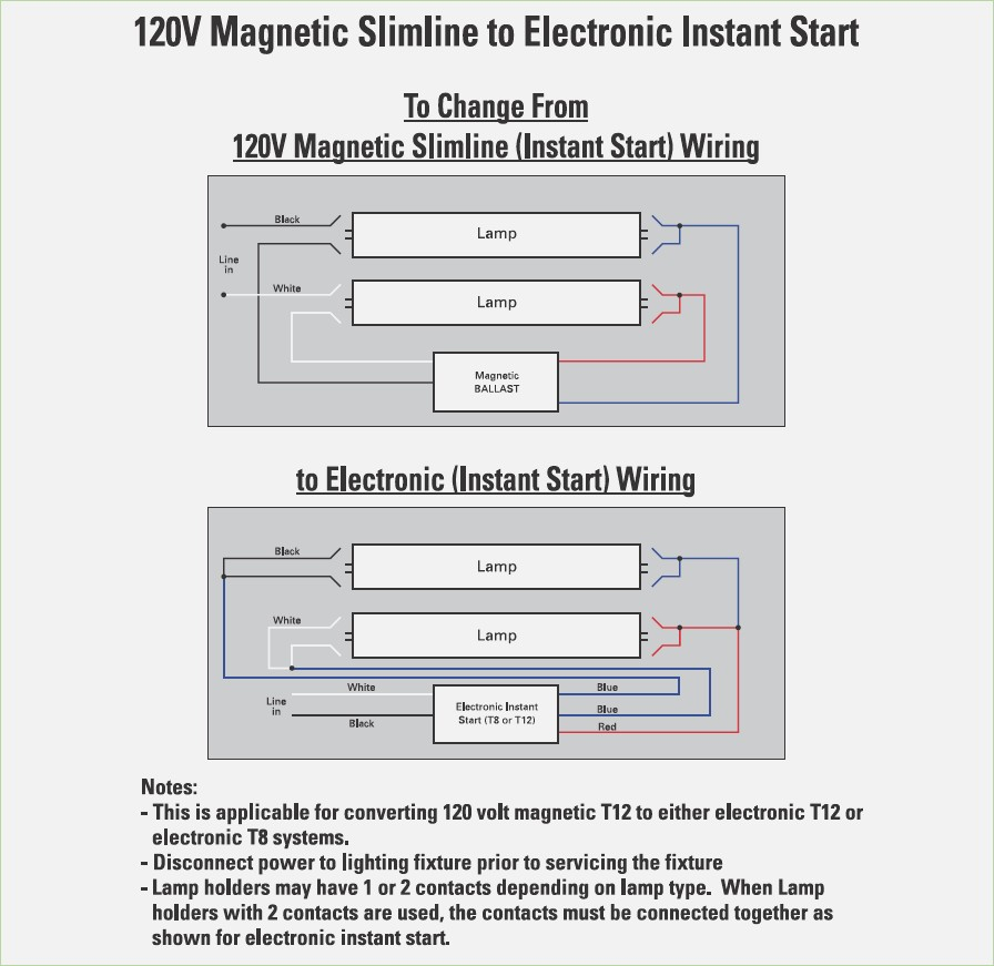
1 lamp t12 ballast wiring diagram. October 11, 2021 on t12 to t8 ballast wiring diagram. The yellow wires are, for lack of a better description, are shared so pin 1 of lamp 1 and pin 1 of lamp 2 go one yellow wire. However, it does not mean connection between the wires.
Assortment of fluorescent ballast wiring diagram. Notice how both the red and blue wires go to one lamp. On the other hand, this diagram is a simplified variant of the structure.
The doe ballast ruling effective april 1, , prevents the sale of 4 foot and 8 foot lamp. Ballast manufacturer recommends no more than 25′ wiring. Rapid start ballasts can only be wired in series according to the diagram on the ballast.
The doe ballast ruling effective april 1, , prevents the sale of 4 foot and 8 foot lamp. Proline® t12 ballasts have the same wiring. The yellow wires are, for lack of a better description, are shared so pin 1 of lamp 1 and pin 1 of lamp 2 go one yellow wire.
Cut the old ballast wiring. This diagram gives information of circuit. Wiring diagram consists of numerous detailed illustrations that show the relationship of assorted things.
Occasionally, the wires will cross. Ballast manufacturers like phillips offer technical support, including a telephone number to call for assistance. However it does not mean connection between the wires.
But, it does not mean connection between the wires. It is intended to aid each of the common person in developing a proper program. It makes the process of assembling circuit easier.
Sometimes, the cables will cross. Ballast wiring diagram explained t12 2 bulb. 2 lamp t12 ballast wiring diagram you will need a comprehensive skilled and easy to know wiring diagram.
2 lamp rapid start to. According to earlier the lines in a 2 lamp t12 ballast wiring diagram signifies wires. It contains guidelines and diagrams for different varieties of wiring techniques along with other items like lights, windows, and so on.
Wiring of fluorescent lamp circuit in electrical installation work. It consists of guidelines and diagrams for various types of wiring strategies along with other products like lights, home windows, and. Replace the fluorescent light ballast in four steps.
Connect the ballast to the power from the breaker panel by wiring the black wire from. According to earlier, the lines in a 2 lamp t12 ballast wiring diagram signifies wires. At times, the wires will cross.
Rapid start ballasts can only be wired in series according to the diagram on the ballast. Ballast wiring diagram (shows how the ballast is wired to the lamps) ballast wiring diagram. Here's a larger view of the wiring diagram.
As stated earlier, the lines at a t12 ballast wiring diagram represents wires. It contains guidelines and diagrams for different varieties of wiring techniques along with other items like lights, windows, and so on. Fixture uses two 4 ft, 34 watt, t12 bulbs.
Remove the bulbs and fluorescent light fixture cover. Proline® t12 ballasts have the same wiring and mounting requirements as standard magnetic ballasts and provide up to 20% energy savings by simply replacing the ballast. Pin 2 of lamp 1 and pin 2 of lamp 2 go to the other yellow wire.
Remove the ballast from the. As stated earlier, the lines at a t12 ballast wiring diagram represents wires. Unplug the fixture or turn off the power at the main panel.
This led emergency ballast installs within the t5 t8 lighting fixture and provides emergency lighting in the event of a power loss. But, it does not imply connection between the cables. Proline® t12 ballasts have the same wiring and mounting requirements as standard magnetic ballasts and provide up to 20% energy savings by simply replacing the ballast.
Injunction of 2 wires is usually indicated by black dot in the junction of 2 lines. Wiring diagrams and descriptions to help you understand fluorescent ballasts, a fluorescent tube circuit includes a ballast, wires, lampholders, and the tubes. I purchased a ge proline ballast replacement for a two lamp flourescent fixture, 48 each lamp.
So the neutral wire is. There’ll be principal lines which are represented by l1, l2, l3, and so on. Ge mvp t12 ballasts have the same wiring and mounting requirements as.
The diagram offers visual representation of a electric structure. There’ll be primary lines which are represented by l1, l2, l3, and so on. 4 lamp t8 ballast wiring diagram.
Ballast operates the fluorescent lamp (s) as intended. Injunction of two wires is usually indicated by black dot to the intersection of 2 lines. For example, if the a.c.

Find Out Here Ge T12 Ballast Wiring Diagram Sample

Changing fluorescent fixture from T12 to T8 Community Forums
20 Images Emergency Ballast Wiring Diagram

B240R120RH Triad® Electronic Fluorescent Ballast (1/2) F403430 T12 Lamps
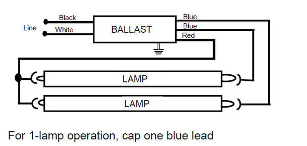
B260I120MA Universal Electronic Fluorescent T12 Ballast
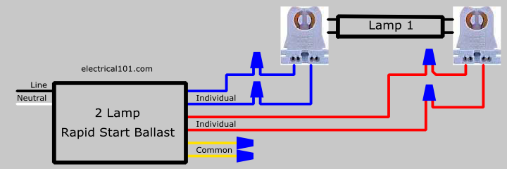
Vedios T12 Ballast Wiring Diagram

2 Lamp T12 Ballast Wiring Diagram Collection Wiring Diagram Sample
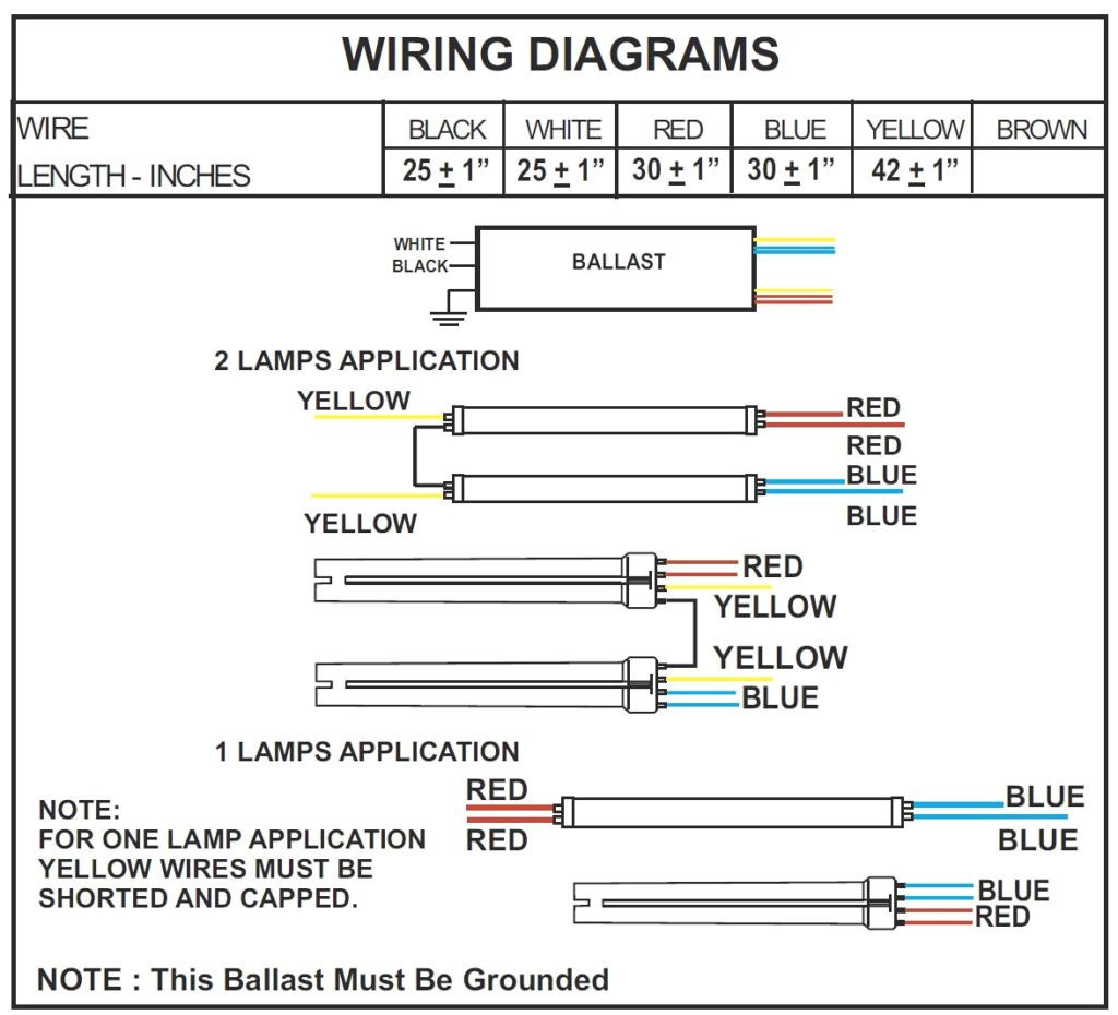
2 Lamp T12 Ballast Wiring Diagram Collection Wiring Diagram Sample
[DIAGRAM] 2l T12 Ballast Wiring Diagram
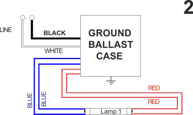
Single Lamp T12 Ballast Wiring Diagram Complete Wiring Schemas
I am replacing a single lamp T12 fixture ballast with an electronic ballast. The new
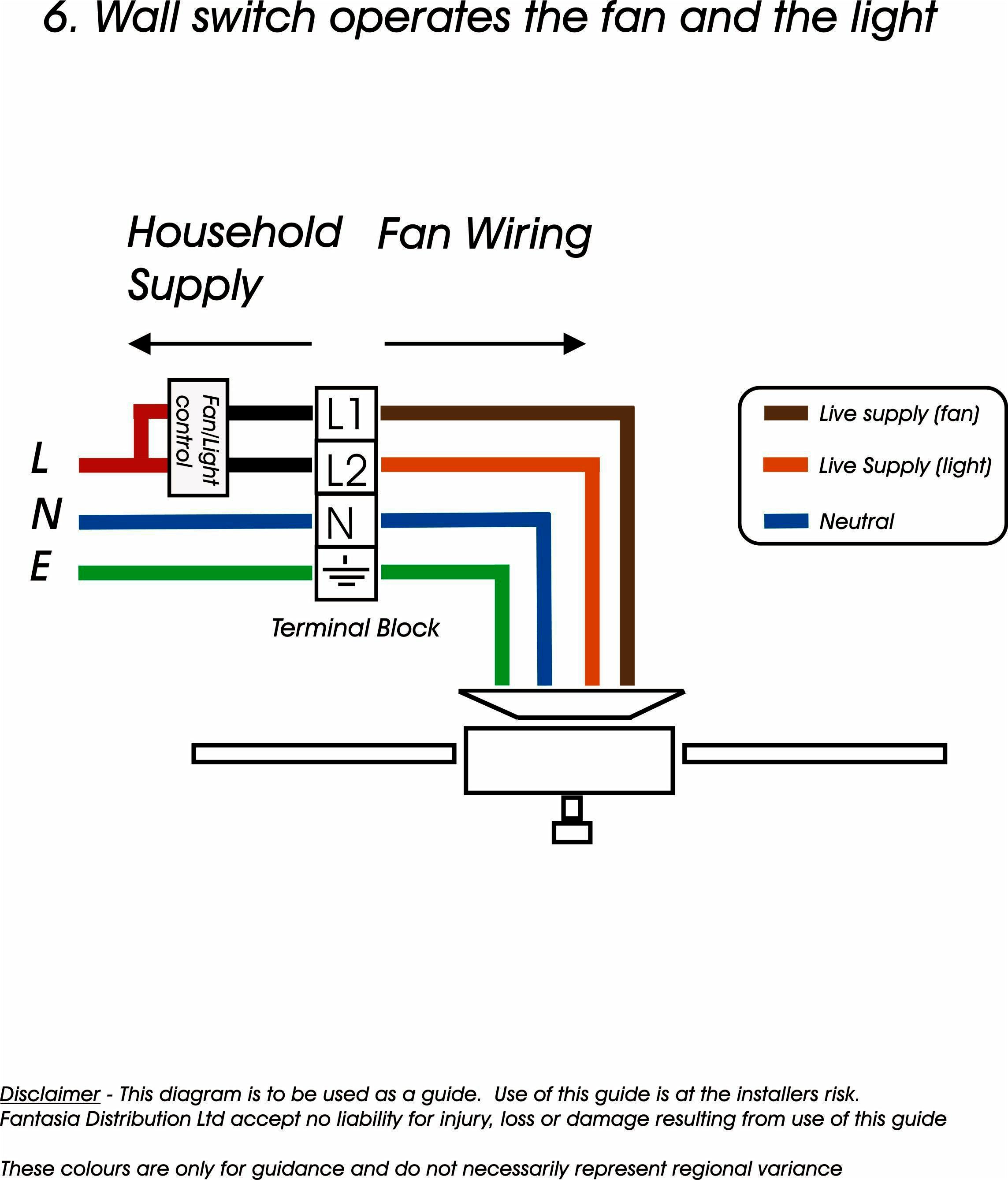
T12 Ballast Wiring Diagram Wiring Diagram

2 Lamp T12 Ballast Wiring Diagram

What is the ballast wiring set up when converting from a T12 ballast to a T8 electronic
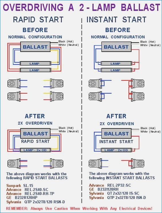
2 Lamp T12 Ballast Wiring Diagram Collection Wiring Diagram Sample

Ballast Wiring Diagram Explained T12 2 Bulb

T12 Electronic Ballast Wiring Diagram


