Pump Control Wiring Diagram
Simply plug the pumps into the provided receptacles. The wires from the pressure switch connect to the electrical input terminals, usually called l1 and l2. the wires heading to the well's pump motor connect to terminals with a.

Sump Pump Wiring Diagram Sample
Green = ground blue = run brown = start black = common you will see that

Pump control wiring diagram. Franklin well pump control box wiring diagram wiring diagram is a simplified normal pictorial representation of an electrical circuit. Duplex pump control panel wiring diagram inspirational dump trailer. The liquid rises until the top float.
Pump control panel wiring diagram schematic. We’re going to look at a progression of straightforward pump control arrangements using float switches. So use a larger gauge wire for lower voltage drop.
Control circuit may not be at the same voltage as the power circuit. Wiring diagram of 2 float switch for two tanks wiring diagram of 3 motors diagram guitar fender also well and septic systems diagnostics. No toggling between local and remote operation.
Sump pump control wiring diagram. The wiring connection of submersible pump control box is very simple. Breakers) generator provisions motor protection (fuses, breakers, thermal) motor controls (starters, soft starters, drives) transformers logic (relay, controllers, plc) alarm dialers / telemetry pilot devices intrinsically safe
Economy duplex sump pump control the duplex control provides alternating operation of two volt pumps. 220v 3 wire well pump wiring diagram. Submersible pump control box wiring diagram.
These instructions and diagrams will serve to teach you the basics of float switch control wiring. As shown in the diagram, you will need to power up the thermostat and the 24v ac power is connected to the r and c terminals. Water pump wiring troubleshooting well installation wire a three 120v how to 220 pressure switch terry love control install and replacement on sanborn 110 float submersible diagrams square d 40 60 psi plastic exterior tameson com i am rewiring can you help auto restart v table level controller circuit using pumps an overview 3 vs 4 catalogue.
Float switch wiring diagram for water pump. They certainly dont apply in all scenarios especially when additional control equipment is needed to handle large motors. 4oz bottle round metal 17oz bottle round plastic.
This diagram is for the circuit to empty a tank, using two normally open float switches and a two pole changeover relay. How to create a pump control circuit to automatically empty a tank. The color of wire r is usually red and c is black.
Red and yellow might indicate that it is a 2 wire 220 volt pump. Electrical diagrams motor phase pump with manual automatic float court in 2020 diy electrical basic electrical wiring electrical wiring. Black wires go to black wires, and the green wire (the ground) goes to the ground wire.
Wiring diagrams for all control and electrical panels. Connect the flow switch wiring to the control panel (ref control wiring diagram in. The bottom switch will be closed provided the liquid is above that switch point.
Deep submersible well pumps will be either 2 wire or 3 wire well pumps and 3 wire well pumps will need a separately installed control box. These two connections will ensure that there is power to the thermostat that you are. Assortment of submersible pump control box wiring diagram.
Submersible pump control box wiring diagram for 3 wire single phase submersible pump submersible well pump submersible. Phase controller wiring phase failure relay diagram relay electrical panel wiring failure. Gb subdrive75/00/50 constant pressure controller installation manual contents controller model franklin electric motor model rated power kw hp,5.
It consists of directions and diagrams for different types of wiring techniques as well as other items like lights, windows, and so forth. Contractor located in the control panel (ref control wiring diagram in the control panel). It shows the elements of the circuit as simplified forms and also the power as well as signal links between the devices.
We’ll look at single and double switch arrangements and how to wire them, and then look at equivalent circuits using kari series float switches. Control panel for 1 h p submersible pumps with timer ltems t 1050 ewatercart com. Inspect the control box's wiring diagram located on the back of the lid.
Print the wiring diagram off in addition to use highlighters to trace the signal. 2 wire well pump diagrams are slightly. 12 awesome wiring diagram for 220 volt submersible pump ideas bacamajalah in 2020 submersible well pump well pump submersible pump.
It shows the elements of the circuit as streamlined forms, and the power and signal connections in between the devices. Diagrams shall (e) electrical schematic diagram of the pump station as supplied, prepared in. They certainly don’t apply in all.
Franklin electric pump controller model 2823 wiring diagram. Find all fire pump controller drawings as well as jockey pump controller, remote alarm panel, and low suction shutdown controller drawings here. The wiring diagram identifies the electrical terminals and lists their functions.
Control box wiring diagrams (continued). Wiring diagram includes many detailed illustrations that display the relationship of various items. Submersible pump control box wiring diagram for 3 wire single phase submersible pump submersible well pump electrical circuit diagram.
When the voltage of the control and power circuits is the same, it is referred to as common control. A wiring diagram is an easy visual representation in the physical connections and physical layout of an electrical system or circuit. C is known as the common terminal.
2 wire well pump wiring diagram.
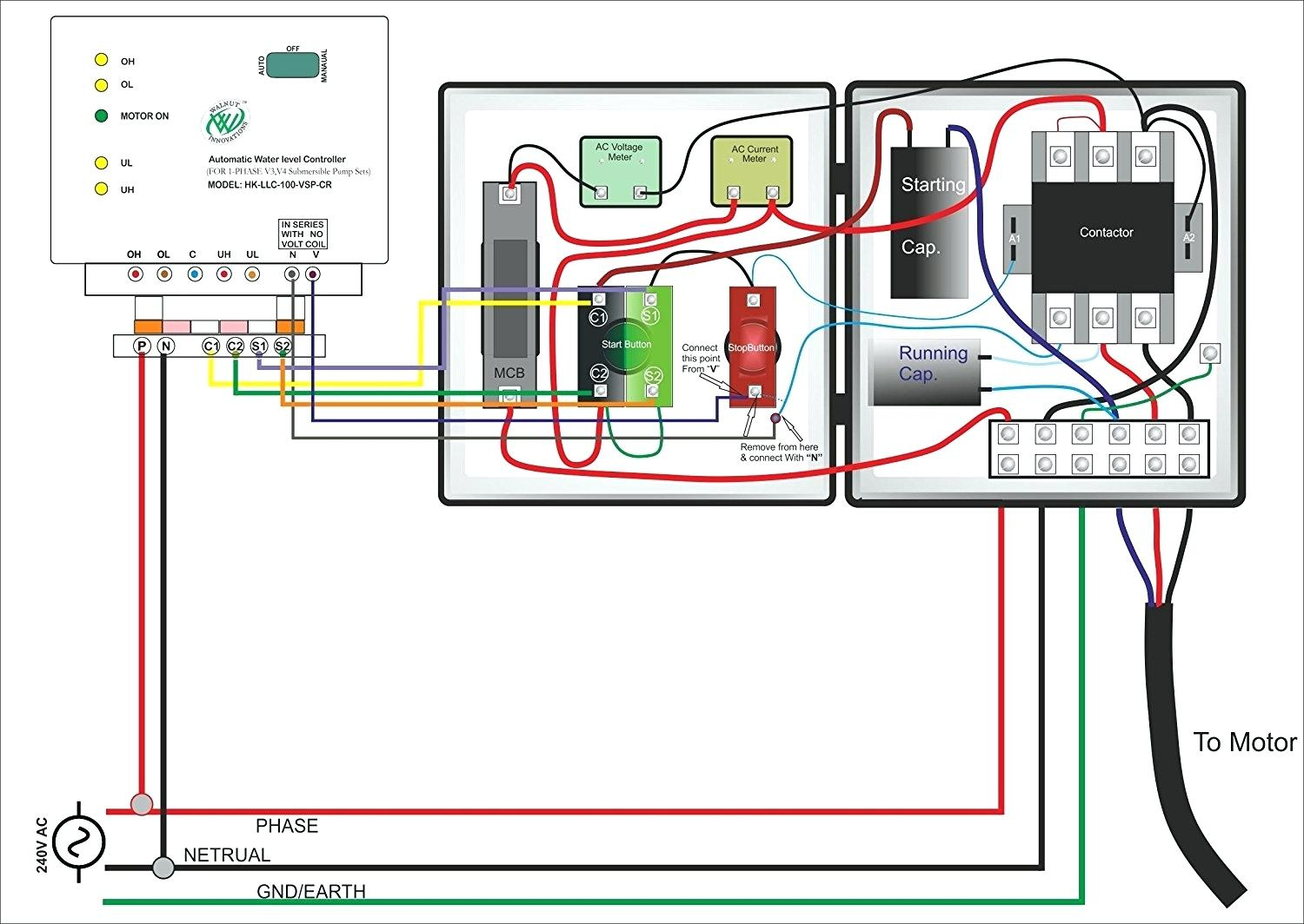
3 Wire Well Pump Wiring Diagram Wiring Diagram
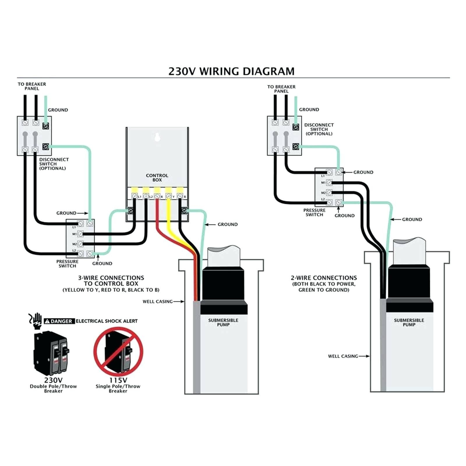
3 Wire Submersible Well Pump Wiring Diagram Wiring Diagram

Find Out Here Duplex Pump Control Panel Wiring Diagram Download
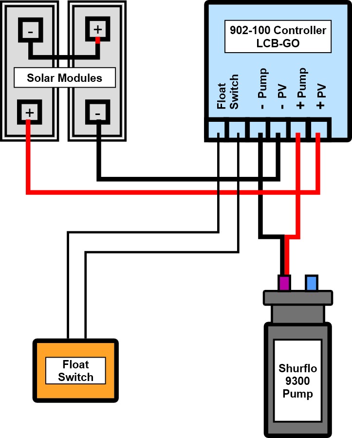
Shurflo 9300 Solar Well Pump Controller LCBGO 902100 Instructions

Lead Lag Pump Control Wiring Diagram Free Wiring Diagram
Submersible Pump Control Box Wiring Diagram For 3 Wire Single Phase Electrical Online 4u

Lead Lag Pump Control Wiring Diagram Download Wiring Collection

Submersible water pump control box wiring diagram🔥 YouTube

Munro Pump Wiring Diagram Download

Lead Lag Pump Control Wiring Diagram Free Wiring Diagram
Wiring diagram of the pump controller. Download Scientific Diagram
Shurflo 9300 Solar Well Pump Info

Find Out Here Duplex Pump Control Panel Wiring Diagram Download
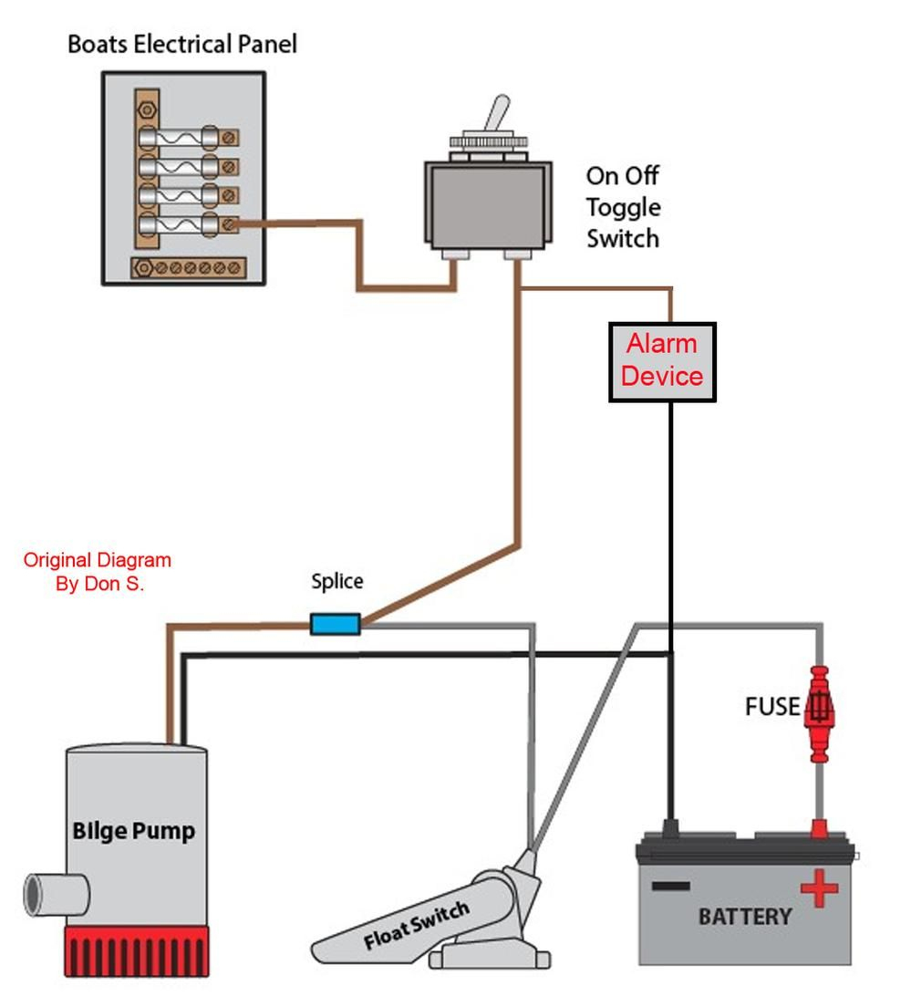
Bilge Pump Float Switch Wiring Diagram Cadician's Blog
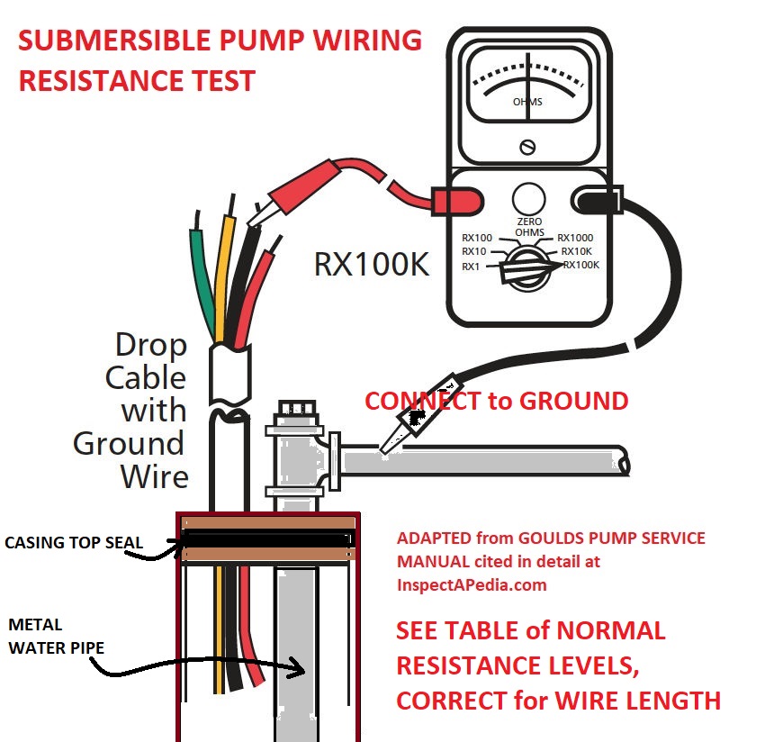
Water Pump Wiring Troubleshooting & Repair

3 Phase Submersible Pump Wiring Diagram Collection

Find Out Here Duplex Pump Control Panel Wiring Diagram Download

Submersible Well Pump Wiring Diagram Gallery

Find Out Here Duplex Pump Control Panel Wiring Diagram Download

